![]()
NOTE: This is the original manual draft for the Mosquito Air kit helicopter and not a current approved and updated manual. Aviators and pilots should follow the factory recommendations and use their latest release of operators manual. This manual was shared directly with Redback Aviation via CD from John Uptigrove (deceased) around the year 2000. For further information please contact Composite FX in the USA
![]()
INDEX
1. INTRODUCTION
2. SPECIFICATIONS
- A. Airframe
- B. Rotors
- C. Drive
- D. Power Plant
- E. Fuel
3. OPERATIONAL LIMITS
- A. Speed
- B. Rotor Speed
- C. Engine
- D. Weight
- E. Altitude
- F. Flight Maneuvers
4. STANDARD OPERATING PROCEDURES
- A. General
- B. Flight Speeds
- C. Flight Operation
5. EMERGENCY OPERATING PROCEDURES
- A. General
- B. Emergency Conditions
- C. Power Failure During Climb, Cruise or Descent
- D. Power Failure During Hover
- E. Tail Rotor Failure During Climb, Cruise or Descent
- F. Tail Rotor Failure During Hover
- G. Gauge Failure During Flight
6. INSPECTIONS
- A. General
- B. Preflight Inspection
- C. Postflight Inspection
- D. Periodic Maintenance
7. SAFETY AND MAINTENANCE SUPPLEMENT
8. FLIGHT ENVELOPE
1. INTRODUCTION TO THE MOSQUITO AIR KIT HELICOPTER
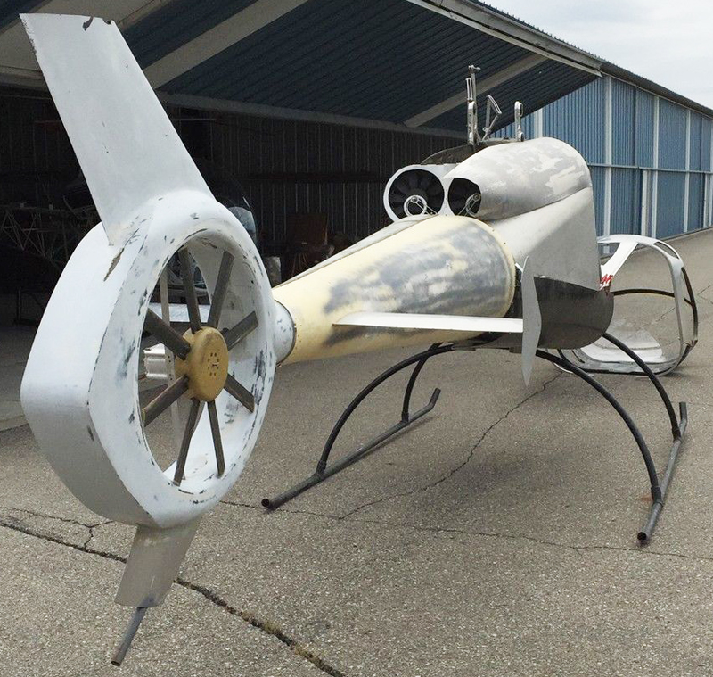
Congratulations on your purchase of the Mosquito Air Kit Helicopter, one of the lightest manned helicopters in the world. With the proper care and attention to safety it will provide you with many hours of enjoyable flight.
This handbook is intended as a general guide for operation and maintenance of the Mosquito Ultralight helicopter. It is not intended to replace training by a certified flight instructor in any way, nor is it intended to replace the knowledge and skills of a properly trained aircraft mechanic.
Although it is light and small, the Mosquito is a real helicopter in every sense, with controls, drive and rotor systems and capabilities all similar to its bigger companions. It therefore requires the same amount of respect and consideration for safety and integrity that would be required of a larger helicopter.
In order to fly the Mosquito Air kit helicopter, potential pilots must receive proper training. It is strongly recommended that pilots be fully trained to private pilot status in a small training helicopter such as a Robinson R22. Training to student pilots status is considered the minimum acceptable amount of training required.
Once the kit is completed, or during construction, the finished Mosquito Air kit helicopter should be inspected by a certified aircraft mechanic to ensure proper construction techniques and procedures have been followed and that the aircraft is airworthy.
NOTICE
The owner must be aware at all times that the responsibility for airworthiness of the helicopter, pilot competency and flight safety rest solely with the owner/operator. Operation of the helicopter by an inadequately trained pilot could result in severe injury or death! Operation of the helicopter when it is not fully air worthy could result in injury or death!
The owner/operator assumes all risk and responsibility for the operation of the Mosquito helicopter. The seller neither accepts or assumes any liability through the publication of this handbook. Information within this handbook is subject to change without notice.
2. SPECIFICATIONS
A. Airframe
- Length (airframe): 16 ft
- Length (overall): 20 ft
- Height: 83 in
- Width: 71 in
- Materials: 6061-T6 Aluminum/Low Modulus Carbon Fiber
B. Rotors
- Main Rotor:
- Articulation: Semirigid underslung teeter
- Diameter: 18 ft
- Speed: 500 rpm
- Chord: 7.75 inch
- Twist: None
- Pre-cone: 2.0 deg
- Tail Rotor:
- Articulation: Semirigid 45 deg offset teeter
- Diameter: 40 in
- Speed: 2450 rpm
- Chord: 4 in
- Twist: None
- Pre-cone: 1.25 deg
C. Drive
- Primary Reduction: 2.45:1 Cog belt
- Secondary Reduction: 4.91:1 Cog belt
- Gear Boxes: 1:1 Spiral Bevel Miter
D. Power Plant
- Model: Zanzottera MZ202
- Type: Two Cylinder, Two Cycle, Dual Ignition, Twin Carburator
- Power: 60 HP @6000 rpm
E. Fuel
- Capacity: 5 US gallons
- Type: Unleaded premium 92 octane
- Consumption: 4 gallon/hr cruise
- Combustion/Lubrication Oil:
- Type: 100% Synthetic 2 Stroke
- Premix Ratio: 40:1
3. OPERATIONAL LIMITS
A. Speed
- Never Exceed (Vne): 90 mph
- Maximum: 70 mph
- Cruise: 60 mph
- Minimum: -20 mph
B. Rotor Speed
- Never Exceed (Red): 110% (550 rpm)
- High Caution (Yellow): 104% (520 rpm) – 110% (550 rpm)
- Normal Operation (Green): 96% (480 rpm) – 104% (520 rpm)
- Low Caution (Yellow): 90% (450 rpm) – 96% (480 rpm)
- Never Below: (Red) 90% (450 rpm)
C. Engine
- Speed:
- Maximum (Red): 108% (6500 rpm)
- High Caution (Yellow): 104% (6250 rpm) – 108% (6500 rpm)
- Operating (Green): 96% (5800 rpm) – 104% (6250)
- Cylinder Head Temperatures:
- Maximum: 500 F
- Caution: 400 F – 500 F
- Operating: 300 F
- Exhaust Gas Temperature:
- Maximum: 1450 F
- Caution: 1350 F – 1450 F
D. Weight
- Maximum Take Off Weight: 530 lb
- Maximum Pilot Weight: 250 lb
- Empty Weight: 253 lb
E. Altitude
- Maximum Hover in Ground Effect: 80000 ft density altitude
- Maximum Hover out of Ground Effect: 6000 ft density altitude
- Maximum Operational Altitude: 8000 ft density altitude
F. Flight Maneuvers
- Acrobatic flight prohibited
- Flight during icing conditions prohibited
- Forward pushovers (sudden applications of full forward cyclic) are prohibited. The resulting low or negative rotor loading coupled with large control movements can result in loss of rotor control.
4. STANDARD OPERATING PROCEDURES
A. General
Information provided in the procedures section is based on standard helicopter operating procedures and experience gained through flight testing of the Mosquito Air kit helicopter. The seller makes no claims to the accuracy of suitability of the following procedures, nor has any regulating body approved of them. They are provided for informational and educational purposes only.
B. Flight Speeds
- Maximum Rate of Climb: 35 mph
- Maximum Range: 55 mph
- Power On Landing Approach: 45 mph
- Power Off Landing Approach: 35 mph
C. Flight Operation
Prior to Startup:
- Perform complete preflight checks (see “6.0 Inspections”)
- Fuel valves – ON
- Fasten seat belt
- Check full travel of all controls for smooth operation
- Collective full down, cyclic neutral, foot pedals neutral
- Choke – ON
- Check area all clear
Engine Startup:
- Master Switch – ON
- Throttle slightly open
- Engage starter button
- Allow engine to idle at 1600 – 2000 rpm until cylinder head temp gauges start to show temperature rise
- Flip master switch to single ignition operation. Digital tachometer should stop reading rpm and return to hour reading.
- Listen for slight drop in rpm.
- Return master to dual ignition setting.
Rotor Run up:
- Slowly increase throttle to 100% rpm.
- Monitor gauges for increase in CHT and EGT.
- Rotor/Engine Tach should both read 100%.
- Digital tach should read 6000-6100 rpm.
- Cut throttle to idle.
- Monitor Rotor/Engine tach for split in rotor vs. engine rpm to verify correct operation of sprague clutch.
Take Off:
- Liftoff should always be done while facing into the wind.
- Slowly increase throttle to 100% rpm.
- Raise collective to hover position.
- Maintain rotor rpm within upper green range.
- Manual throttle setting should not require significant adjustment during lift into hover.
- If excessive adjustment is required, readjust location of throttle cables in correlator slots as required.
- Maintain hover at 2 to 3 feet AGL.
CAUTION!
⬤ Do not hover below this level unless helicopter is equipped with a training boom.
⬤ Wind gusts when hovering within inches of the ground can cause a pad can catch during the resulting lateral movement resulting in tip over.
⬤ Monitor gauges for operation in within normal operating zone.
⬤ Move cyclic forward and accelerate up to climb speed while maintaining heading into the wind.
⬤ Maintain speed/altitude within safe zone of Height Velocity curve at all times (refer to H-V diagram).
⬤ Maintain rotor rpm in 100% to 104% rpm green range at all times.
Cruise:
- Maintain rpm in 100% to 104% range
- Avoid excessive control excursions.
- Fly smoothly.
- Monitor engine temperature gauges at all times.
![]()
Approach and Landing:
- Approach to landing should always be done into the wind.
- Maintain forward speed above 20 mph at all times during decent.
CAUTION!
⬤ Never descend at low or zero forward airspeed to avoid “settling with power” or “vortex ring state” flight mode.
⬤ Gently flare and come to a hover at 5 to 10 feet AGL.
⬤ Gradually reduce collective until ground contact.
⬤ Maintain rpm in 100% to 104% range at all times.
⬤ Continue to reduce collective until fully settled.
Shut Down:
- Reduce throttle until engine is at idle.
- Idle engine for approximately 1 minute to facilitate cooling.
- Throttle – FULL OFF
- Master switch – OFF
5. EMERGENCY OPERATING PROCEDURES
A. General
Information provided in the procedures section is based on standard helicopter operating procedures and experience gained through flight testing of the Mosquito. The seller makes no claims to the accuracy of suitability of the following procedures, nor has any regulating body approved of them. They are provided for informational and educational purposes only.
B. Emergency Conditions
Emergency flight procedures should be followed whenever a power or drive system failure is indicated during flight. These conditions will be indicated by the following:
- Sudden change in noise level
- Sudden onset of abnormal noise
- Sudden yaw to the left (engine failure)
- Sudden yaw to the right (tail rotor failure)
- Engine/Rotor tachometer in low yellow or red zone
- Sudden change in vibration level or frequency
C. Power Failure During Climb, Cruise or Descent
- Lower collective lever immediately
- Apply full right pedal
- Maintain rotor rpm in green zone adjust collective accordingly
- Adjust pedal to maintain forward heading
- Establish decent glide at 35 to 40 mph
- Select landing spot so that landing approach will be into the wind
- At 30 feet begin flare to slow forward speed until reduced to a minimum at 5 to 10 feet AGL.
- At 5 to 10 feet apply forward cyclic to level attitude.
- Pull collective to cushion landing.
- Maintain heading into the wind.
- Avoid touchdown with lateral movement.
D. Power Failure During Hover
- Apply full right pedal
- Allow aircraft to settle
- Increase collective at 3 to 5 feet to cushion landing
E. Tail Rotor Failure During Climb, Cruise or Descent
- Lower collective lever immediately to enter autorotation
- Establish decent glide at 35 to 40 mph
- A small amount of power may be used during the decent if needed to extend glide.
- At 30 feet close throttle and perform emergency autorotation landing as outlined in section C above.
F. Tail Rotor Failure During Hover
- Close throttle immediately
- Allow aircraft to settle
- Increase collective at 3 to 5 feet to cushion landing
G. Gauge Failure During Flight
- Rotor Tachometer
- Maintain engine tachometer in green zone and perform normal power on landing as soon as possible.
- Maintain collective in normal decent position to prevent rotor from entering autorotation.
- Engine Tachometer
- Maintain rotor tachometer in green zone.
- Use backup digital tachometer as required.
- Land as soon as possible.
- EGT/CHT gauge
- Maintain normal operation and land as soon as possible.
CAUTION!
6. INSPECTIONS
A. General
To make flight as safe as possible it is essential to conduct a thorough pre-flight and post-flight inspection before and after every flight.
Pre-flight inspections provide invaluable insight to impending failure through signs such as loose bolts, rivets, fittings, wire connections, belts or bearings; cracking in structural, engine or other components; chafing or rubbing in areas not intended to contact. Post flight inspections are used to feel for excess heat coming from bearings or gear boxes which can indicate impending failure.
Preflight inspection should be conducted in an orderly consistent fashion to ensure all points are inspected each time. The following list is provided as a minimum requirement for flight inspections and is not intended to be a complete comprehensive preflight or post flight schedule.
The seller assumes no responsibility for the completeness or suitability of the following list and is provided as a guideline for educational purposes only. Remember that the responsibility for the safety of each flight rests solely with the owner/operator of the aircraft.
B. Preflight Inspection
Start at the front left of the aircraft and finish at the front right, progressively circling the aircraft.
Left Side:
⬤ Toe pad – secure, rivets secure, bracket integrity (free of nicks, cracks)
⬤ Foot pedal bell crank – pivot bearing play, pivot bearing retention bolts tight, pivot bolt tight, support rivets secure, support integrity, pitch links rod end play (no axial movement), rod end bolts secure
⬤ Foot pedals – full and smooth pedal travel, full tail rotor movement, rod end play, bolts tight, cable bolt tight, rivets secure, pedal integrity
⬤ Foot pedal support – rivets secure, support solid, support integrity
⬤ Instrument panel – instruments secure, wire sockets fully engaged, pitot/static tubing in place, rivets secure, bracket integrity, panel integrity
⬤ Front leg brace connection – bolt tight, brace reinforcement rivets secure, brace and reinforcement integrity (particularly at bend)
⬤ Cyclic lever – full and smooth travel in all directions, pivot bearing play, pivot bolt tight, rod ends secure, support rivets, support integrity, push pull tube rivets secure
⬤ Seat – support rivets secure, support uprights and plate integrity, rubber mount integrity and condition, rubber mounts secure
⬤ Front leg – integrity (fiberglass cracking or delamination on underside and in vicinity of brace bolt and mast connection), mast mount bracket integrity, rivets secure
⬤ Rear left leg – same as for front leg
⬤ Rear left leg strut connections – connector rivets secure, tube end rivets secure, connector integrity, tube end integrity, strut end integrity (cracking, delamination in carbon fiber struts)
⬤ Rear left leg brace bolt connection – same as for front leg brace bolt connection
⬤ Rear left foot pad – same as for toe pad
⬤ Collective lever – full and smooth travel, support/slave lever/torque tube/correlator/lever integrity, all rivets secure, rod end play, full travel of throttle, cable sleeve secure, throttle splitter secure, cable integrity (no fraying)
⬤ Mixing box – (look into control entry hole or up from under mast), collective slave lever integrity (inside mast), rod end play, rod end bolts tight, component integrity
⬤ Engine mounts – mount and mount bracket integrity, rubber bushing seating and condition, mount plate integrity, mount bolts tight
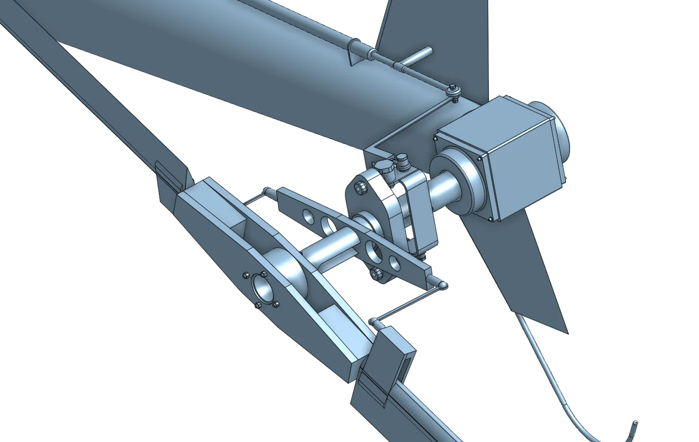
⬤ Engine – carburetors secure, carburetor mount condition, throttle cable secure, CDI mount condition, all wiring (regulator, instrument senders, plug etc) secure and in good condition, oil seepage, fan integrity, fan shroud secure, exhaust and exhaust mount integrity
⬤ Primary reduction – centrifugal clutch secure, sprocket/belt condition, belt tension, sprague clutch (spin and engage reduction), bearing play (move sprocket edge up and down), bolts tight, component integrity
⬤ Drive shafts – bolts tight, shaft and flex plate integrity, coupling integrity, set screws tight
⬤ Tail boom support/brace – support/brace integrity, rivets secure
⬤ Upper strut connector – integrity, bolts tight, rivets tight
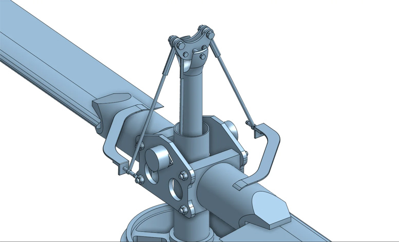
⬤ Splitter gear box – bolts tight, oil leaks, oil filler plug secure, bearing play (move coupling on shaft back and forth)
⬤ Swash plate – bolts tight (marks on bolts in correct position), rod end play, bearing play (move stationary plate bolt in slot back and forth), component integrity (lift collective full up to check push rods and rod ends)
⬤ Sprocket support/braces – support/brace integrity, rivets secure, bolts tight
⬤ Secondary reduction – sprocket/belt condition, belt tension, bolts tight, bearing play (move upper coupling back and forth, move rotor shaft back and forth)
⬤ Rotor head – hub plate/blade grip/blade root integrity, bolts tight, rod end play, push tube play (move push tube back and forth), butterfly lever bearing play, controls components integrity (lift collective full up to inspect push tube/push rods
⬤ Main rotor blades – integrity (scratches, cracking, disbonding, tip cap security, cleanliness)
⬤ Main mast – integrity (scratches, cracking)
⬤ Tail boom – integrity (cracking, delamination)
⬤ Rear strut connectors – bolts tight, connector integrity
⬤ Tail rotor gear box –bolts tight, oil leaks, oil filler plug secure, bearing play (move shaft back and forth)
⬤ Tail rotor controls – bolts tight, rod end play, shaft clean and greased under control bearing sleeve, component integrity, rivets secure, control cable integrity
⬤ Tail rotor blades – pivot nut cotter pin, integrity (scratches, cracking, tip foam, cleanliness)
Right Side:
⬤ Tail rotor guard – integrity, bolts tight
⬤ Rear strut connectors – same as left
⬤ Rear strut – integrity, rivets secure
⬤ Tail boom support/brace – same as left
⬤ Upper strut connector – same as left
⬤ Engine – mount bolts tight, starter secure, battery secure, wiring secure, EGT senders secure, exhaust and exhaust mount integrity, oil seepage
⬤ Engine mounts – same as left
⬤ Drive shafts – same as left
⬤ Swash plate – feel through inspection hole
⬤ Sprocket support/brace – same as left
⬤ Rotor head – right side component integrity
⬤ Rear right leg/strut connections/brace connection/foot pad – same as left
⬤ Seat – same as left
⬤ Cyclic lever – component integrity
⬤ Front leg brace bolt connection – same as left
⬤ Foot pedals/support/bellcrank – same as left
C. Postflight Inspection
Immediately following shut down, after all rotating components have stopped moving the following checks should be made. Note that some heat from bearings is normal and is expected. Get to know the expected warmth from the bearings through habitually performing post flight checks. The onset of noticeable excess heat will warn of impending bearing failure.
⬤ Main rotor bearings – place hand at top of mast under rotor shaft sprocket
⬤ Main rotor hub teeter bearings– feel hub plates at teeter bearing
⬤ Main rotor feather bearings – feel inner and outer pivot blocks
⬤ Secondary reduction driving sprocket bearings – feel upper and lower bearing housings
⬤ Splitter gear box
⬤ Tail boom steady bearings – feel along tail boom for each bearing
⬤ Tail rotor gear box
⬤ Tail rotor hub
⬤ Tail rotor feather bearings
D. Periodic Maintenance
The following components require periodic attention to ensure proper lubrication.
⬤ Grease lubrication points SLOWLY to prevent pushing out grease seals.
⬤ Watch for a small amount of grease to emerge on opposite end of bearing.
⬤ Remove excess grease and clean area.
⬤ All points should be greased every 10 hours of flight operation.
- Main rotor teeter bearings
- Main rotor inner feather bearing
- Main rotor outer feather bearing
- Tail rotor feather bearings
Tail rotor and splitter gear box oil should be checked every 5 hours. With the aircraft level, remove the filler plug. Hold a small, clean, 3 inch length of wire level and insert it into the filler hole approximately ¼ ” past the inner edge of the hole.
Tilt it down until the tip is approximately level with the bottom of the hole and remove. A drop of oil should remain on the end of the wire. If the wire is dry, slowly add oil until it begins to run out of the hole. Reinstall fill plug.
7. SAFETY AND MAINTENANCE SUPPLEMENT
⬤ Always store the aircraft in an enclosed, dry space to prevent corrosion to critical components of the aircraft.
⬤ Avoid flight through rain or snow. – “If precipitation is encountered during flight dry the aircraft thoroughly on landing and re-grease fittings.”
⬤ Do not carry any additional loads on or under the helicopter. – “Shifting of the load during flight can cause an unbalanced condition resulting in loss of control.”
⬤ Ensure all articles on the aircraft and pilot are secured in place. – “Loose articles can fly back into the tail rotor resulting in damage and potential loss of control.”
⬤ Avoid all abrupt control movements to prevent loss of control or over-stressing critical components.
⬤ Never leave the aircraft with the engine running or rotor spinning.
⬤ Ensure all is clear during rotor run up.
⬤ Never lift the collective lever when the rotor speed is not in the green range. – “Collective pitch at low rotor rpm can lead to excessive flapping resulting in damage to the blade stops and or rotor/rotor head components.”
⬤ Do not use collective pitch to slow the rotor.
⬤ Never begin flight operations with a low fuel condition. – “The fuel tank should be filled at the beginning of each flight.”
8. FLIGHT ENVELOPE
To maximize flight safety all helicopters must only be operated within certain areas of the Height/Velocity regime. If the Mosquito Air kit helicopter is above a level at which it can safely hover-autorotate to the ground (15 feet), it must be at a minimum of 250 feet before hovering is again permitted.
In the event of an engine failure while hovering at altitudes between 15 and 250 feet, the rotor blades will not have sufficient inertia to maintain rpm and there will not be sufficient time for the helicopter to build adequate forward speed for a normal autorotation.
In the event of an engine failure while operating the Mosquito Air kit helicopter at low altitudes and high forward speed will not permit the aircraft to loose sufficient forward speed for a normal autorotational landing prior to contact with the ground.
NOTICE:
Flight operation within the shaded areas of the Height/Velocity diagram can result in serious injury or death!
Flight operation within the shaded areas of the diagram is strictly prohibited!
The post Mosquito Air Kit Helicopter Operators Manual appeared first on Redback Aviation Home Built Helicopters.